| Purchase | Copyright © 2002 Paul Sheer. Click here for copying permissions. | Home |
|
|
| |
IP stands for Internet Protocol. It is the method by which data is transmitted over the Internet.
At a hardware level, network cards are capable of transmitting packets (also called datagrams) of data between one another. A packet contains a small block of, say, 1 kilobyte of data (in contrast to serial lines, which transmit continuously). All Internet communication occurs through transmission of packets, which travel intact, even between machines on opposite sides of the world.
Each packet contains a header of 24 bytes or more which precedes the data. Hence, slightly more than the said 1 kilobyte of data would be found on the wire. When a packet is transmitted, the header would obviously contain the destination machine. Each machine is hence given a unique IP address--a 32-bit number. There are no machines on the Internet that do not have an IP address.
The header bytes are shown in Table 25.1.
Version for the mean time is 4, although IP Next Generation (version 6) is in the (slow) process of deployment. IHL is the length of the header divided by 4. TOS (Type of Service) is a somewhat esoteric field for tuning performance and is not explained here. The Length field is the length in bytes of the entire packet including the header. The Source and Destination are the IP addresses from and to which the packet is coming/going.
The above description constitutes the view of the Internet that a machine has. However, physically, the Internet consists of many small high-speed networks (like those of a company or a university) called Local Area Networks, or LANs. These are all connected to each other by lower-speed long distance links. On a LAN, the raw medium of transmission is not a packet but an Ethernet frame. Frames are analogous to packets (having both a header and a data portion) but are sized to be efficient with particular hardware. IP packets are encapsulated within frames, where the IP packet fits within the Data part of the frame. A frame may, however, be too small to hold an entire IP packet, in which case the IP packet is split into several smaller packets. This group of smaller IP packets is then given an identifying number, and each smaller packet will then have the Identification field set with that number and the Offset field set to indicate its position within the actual packet. On the other side of the connection, the destination machine will reconstruct a packet from all the smaller subpackets that have the same Identification field.
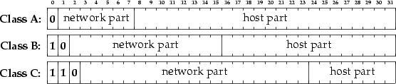
The convention for writing an IP address in human readable form is dotted decimal notation like 152.2.254.81, where each number is a byte and is hence in the range of 0 to 255. Hence the entire address space is in the range of 0.0.0.0 to 255.255.255.255. To further organize the assignment of addresses, each 32-bit address is divided into two parts, a network and a host part of the address, as shown in Figure 25.1.
The network part of the address designates the LAN, and the host part the particular machine on the LAN. Now, because it was unknown at the time of specification whether there would one day be more LANs or more machines per LAN, three different classes of address were created.
Class A addresses begin with the first bit of the network part set to 0 (hence, a Class A address always has the first dotted decimal number less than 128). The next 7 bits give the identity of the LAN, and the remaining 24 bits give the identity of an actual machine on that LAN. A Class B address begins with a 1 and then a 0 (first decimal number is 128 through 191). The next 14 bits give the LAN, and the remaining 16 bits give the machine. Most universities, like the address above, are Class B addresses. Lastly, Class C addresses start with a 1 1 0 (first decimal number is 192 through 223), and the next 21 bits and then the next 8 bits are the LAN and machine, respectively. Small companies tend use Class C addresses.
In practice, few organizations require Class A addresses. A university or large company might use a Class B address but then would have its own further subdivisions, like using the third dotted decimal as a department (bits 16 through 23) and the last dotted decimal (bits 24 through 31) as the machine within that department. In this way the LAN becomes a micro-Internet in itself. Here, the LAN is called a network and the various departments are each called a subnet.
Some special-purposes IP addresses are never used on the open Internet. 192.168.0.0 through 192.168.255.255 are private addresses perhaps used inside a local LAN that does not communicate directly with the Internet. 127.0.0.0 through 127.255.255.255 are used for communication with the localhost--that is, the machine itself. Usually, 127.0.0.1 is an IP address pointing to the machine itself. Further, 172.16.0.0 through 172.31.255.255 are additional private addresses for very large internal networks, and 10.0.0.0 through 10.255.255.255 are for even larger ones.
Consider again the example of a university with a Class B address. It might have an IP address range of 137.158.0.0 through 137.158.255.255. Assume it was decided that the astronomy department should get 512 of its own IP addresses, 137.158.26.0 through 137.158.27.255. We say that astronomy has a network address of 137.158.26.0. The machines there all have a network mask of 255.255.254.0. A particular machine in astronomy may have an IP address of 137.158.27.158. This terminology is used later. Figure 25.2 illustrates this example.
In this section we will use the term LAN to indicate a network of computers that are all more or less connected directly together by Ethernet cables (this is common for small businesses with up to about 50 machines). Each machine has an Ethernet card which is referred to as eth0 throughout all command-line operations. If there is more than one card on a single machine, then these are named eth0, eth1, eth2, etc., and are each called a network interface (or just interface, or sometimes Ethernet port) of the machine.
LANs work as follows. Network cards transmit a frame to the LAN, and other network cards read that frame from the LAN. If any one network card transmits a frame, then all other network cards can see that frame. If a card starts to transmit a frame while another card is in the process of transmitting a frame, then a clash is said to have occurred, and the card waits a random amount of time and then tries again. Each network card has a physical address of 48 bits called the hardware address (which is inserted at the time of its manufacture and has nothing to do with IP addresses). Each frame has a destination address in its header that tells what network card it is destined for, so that network cards ignore frames that are not addressed to them.
Since frame transmission is governed by the network cards, the destination hardware address must be determined from the destination IP address before a packet is sent to a particular machine. This is done is through the Address Resolution Protocol (ARP). A machine will transmit a special packet that asks ``What hardware address is this IP address?'' The guilty machine then responds, and the transmitting machine stores the result for future reference. Of course, if you suddenly switch network cards, then other machines on the LAN will have the wrong information, so ARP has time-outs and re-requests built into the protocol. Try typing the command arp to get a list of hardware address to IP mappings.
Most distributions have a generic way to configure your interfaces. Here, however, we first look at a complete network configuration using only raw networking commands.
We first create a lo interface. This is called the loopback device (and has nothing to do with loopback block devices: /dev/loop? files). The loopback device is an imaginary network card that is used to communicate with the machine itself; for instance, if you are telneting to the local machine, you are actually connecting via the loopback device. The ifconfig ( inter face configure) command is used to do anything with interfaces. First, run
|
/sbin/ifconfig lo down/sbin/ifconfig eth0 down |
to delete any existing interfaces, then run
|
/sbin/ifconfig lo 127.0.0.1 |
which creates the loopback interface.
Create the Ethernet interface with:
|
/sbin/ifconfig eth0 192.168.3.9 broadcast 192.168.3.255 netmask 255.255.255.0 |
The broadcast address is a special address that all machines respond to. It is usually the first or last address of the particular network.
Now run
|
/sbin/ifconfig |
to view the interfaces. The output will be
5 10 |
eth0 Link encap:Ethernet HWaddr 00:00:E8:3B:2D:A2 inet addr:192.168.3.9 Bcast:192.168.3.255 Mask:255.255.255.0 UP BROADCAST RUNNING MULTICAST MTU:1500 Metric:1 RX packets:1359 errors:0 dropped:0 overruns:0 frame:0 TX packets:1356 errors:0 dropped:0 overruns:0 carrier:0 collisions:0 txqueuelen:100 Interrupt:11 Base address:0xe400 lo Link encap:Local Loopback inet addr:127.0.0.1 Mask:255.0.0.0 UP LOOPBACK RUNNING MTU:3924 Metric:1 RX packets:53175 errors:0 dropped:0 overruns:0 frame:0 TX packets:53175 errors:0 dropped:0 overruns:0 carrier:0 collisions:0 txqueuelen:0 |
which shows various interesting bits, like the 48-bit hardware address of the network card (hex bytes 00:00:E8:3B:2D:A2).
The interfaces are now active. However, nothing tells the kernel what packets should go to what interface, even though we might expect such behavior to happen on its own. With UNIX, you must explicitly tell the kernel to send particular packets to particular interfaces.
Any packet arriving through any interface is pooled by the kernel. The kernel then looks at each packet's destination address and decides, based on the destination, where it should be sent. It doesn't matter where the packet came from; once the kernel has the packet, it's what its destination address says that matters. It is up to the rest of the network to ensure that packets do not arrive at the wrong interfaces in the first place.
We know that any packet having the network address 127.??? .??? .??? must go to the loopback device (this is more or less a convention). The command,
|
/sbin/route add -net 127.0.0.0 netmask 255.0.0.0 lo |
adds a route to the network 127.0.0.0, albeit an imaginary one.
The eth0 device can be routed as follows:
|
/sbin/route add -net 192.168.3.0 netmask 255.255.255.0 eth0 |
The command to display the current routes is
|
/sbin/route -n |
( -n causes route to not print IP addresses as host names) with the following output:
|
Kernel IP routing tableDestination Gateway Genmask Flags Metric Ref Use Iface127.0.0.0 0.0.0.0 255.0.0.0 U 0 0 0 lo192.168.3.0 0.0.0.0 255.255.255.0 U 0 0 0 eth0 |
This output has the meaning, ``packets with destination address 127.0.0.0/255.0.0.0 [The notation network/mask is often used to denote ranges of IP address.]must be sent to the loopback device,'' and ``packets with destination address 192.168.3.0/255.255.255.0 must be sent to eth0.'' Gateway is zero, hence, is not set (see the following commands).
The routing table now routes 127. and 192.168.3. packets. Now we need a route for the remaining possible IP addresses. UNIX can have a route that says to send packets with particular destination IP addresses to another machine on the LAN, from whence they might be forwarded elsewhere. This is sometimes called the gateway machine. The command is:
|
/sbin/route add -net <network-address> netmask <netmask> gw \ <gateway-ip-address> <interface> |
This is the most general form of the command, but it's often easier to just type:
|
/sbin/route add default gw <gateway-ip-address> <interface> |
when we want to add a route that applies to all remaining packets. This route is called the default gateway. default signifies all packets; it is the same as
|
/sbin/route add -net 0.0.0.0 netmask 0.0.0.0 gw <gateway-ip-address> \ <interface> |
but since routes are ordered according to netmask, more specific routes are used in preference to less specific ones.
Finally, you can set your host name with:
|
hostname cericon.cranzgot.co.za |
A summary of the example commands so far is
5 |
/sbin/ifconfig lo down/sbin/ifconfig eth0 down/sbin/ifconfig lo 127.0.0.1/sbin/ifconfig eth0 192.168.3.9 broadcast 192.168.3.255 netmask 255.255.255.0/sbin/route add -net 127.0.0.0 netmask 255.0.0.0 lo/sbin/route add -net 192.168.3.0 netmask 255.255.255.0 eth0/sbin/route add default gw 192.168.3.254 eth0hostname cericon.cranzgot.co.za |
Although these 7 commands will get your network working, you should not do such a manual configuration. The next section explains how to configure your startup scripts.
Most distributions will have a modular and extensible system of startup scripts that initiate networking.
RedHat systems contain the directory /etc/sysconfig/, which contains configuration files to automatically bring up networking.
The file /etc/sysconfig/network-scripts/ifcfg-eth0 contains:
5 |
DEVICE=eth0IPADDR=192.168.3.9NETMASK=255.255.255.0NETWORK=192.168.3.0BROADCAST=192.168.3.255ONBOOT=yes |
The file /etc/sysconfig/network contains:
|
NETWORKING=yesHOSTNAME=cericon.cranzgot.co.zaGATEWAY=192.168.3.254 |
You can see that these two files are equivalent to the example configuration done above. These two files can take an enormous number of options for the various protocols besides IP, but this is the most common configuration.
The file /etc/sysconfig/network-scripts/ifcfg-lo for the loopback device will be configured automatically at installation; you should never need to edit it.
To stop and start networking (i.e., to bring up and down the interfaces and routing), type (alternative commands in parentheses):
|
/etc/init.d/network stop( /etc/rc.d/init.d/network stop )/etc/init.d/network start( /etc/rc.d/init.d/network start ) |
which will indirectly read your /etc/sysconfig/ files.
You can add further files, say, ifcfg-eth1 (under /etc/sysconfig/network-scripts/) for a secondary Ethernet device. For example, ifcfg-eth1 could contain
5 |
DEVICE=eth1IPADDR=192.168.4.1NETMASK=255.255.255.0NETWORK=192.168.4.0BROADCAST=192.168.4.255ONBOOT=yes |
and then run echo "1" > /proc/sys/net/ipv4/ip_forward to enable packet forwarding between your two interfaces.
Debian, on the other hand, has a directory /etc/network/ containing a file /etc/network/interfaces. [As usual, Debian has a neat and clean approach.] (See also interfaces(5).) For the same configuration as above, this file would contain:
5 |
iface lo inet loopbackiface eth0 inet static address 192.168.3.9 netmask 255.255.255.0 gateway 192.168.3.254 |
The file /etc/network/options contains the same forwarding (and some other) options:
|
ip_forward=nospoofprotect=yessyncookies=no |
To stop and start networking (i.e., bring up and down the interfaces and routing), type
|
/etc/init.d/networking stop/etc/init.d/networking start |
which will indirectly read your /etc/network/interfaces file.
Actually, the /etc/init.d/networking script merely runs the ifup and ifdown commands. See ifup(8). You can alternatively run these commands directly for finer control.
We add further interfaces similar to the RedHat example above by appending to the /etc/network/interfaces file. The Debian equivalent is,
5 |
iface lo inet loopbackiface eth0 inet static address 192.168.3.9 netmask 255.255.255.0 gateway 192.168.3.254iface eth1 inet static address 192.168.4.1 netmask 255.255.255.0 |
and then set ip_forward=yes in your /etc/network/options file.
Finally, whereas RedHat sets its host name from the line HOSTNAME=... in /etc/sysconfig/network, Debian sets it from the contents of the file /etc/hostname, which, in the present case, would contain just
|
cericon.cranzgot.co.za |
Consider two distant LANs that need to communicate. Two dedicated machines, one on each LAN, are linked by some alternative method (in this case, a permanent serial line), as shown in Figure 25.3.
This arrangement can be summarized by five machines
X, A, B, C, and D. Machines
X, A, and B form LAN 1 on subnet
192.168.1.0/26.
Machines C and D form LAN 2 on subnet
192.168.1.128/26. Note how we use the ``
/26'' to indicate
that only the first 26 bits are network address bits, while the remaining
6 bits are host address bits. This means that we can have at most
![]() IP addresses on each of LAN 1 and 2.
Our dedicated serial link comes between machines B and
C.
IP addresses on each of LAN 1 and 2.
Our dedicated serial link comes between machines B and
C.
Machine X has IP address 192.168.1.1. This machine is the gateway to the Internet. The Ethernet port of machine B is simply configured with an IP address of 192.168.1.2 with a default gateway of 192.168.1.1. Note that the broadcast address is 192.168.1.63 (the last 6 bits set to 1).
The Ethernet port of machine C is configured with an IP address of 192.168.1.129. No default gateway should be set until serial line is configured.
We will make the network between B and C subnet 192.168.1.192/26. It is effectively a LAN on its own, even though only two machines can ever be connected. Machines B and C will have IP addresses 192.168.1.252 and 192.168.1.253, respectively, on their facing interfaces.
This is a real-life example with an unreliable serial link. To keep the link up requires pppd and a shell script to restart the link if it dies. The pppd program is covered in Chapter 41. The script for Machine B is:
5 |
#!/bin/shwhile true ; do pppd lock local mru 296 mtu 296 nodetach nocrtscts nocdtrcts \ 192.168.1.252:192.168.1.253 /dev/ttyS0 115200 noauth \ lcp-echo-interval 1 lcp-echo-failure 2 lcp-max-terminate 1 lcp-restart 1done |
Note that if the link were an Ethernet link instead (on a second Ethernet card), and/or a genuine LAN between machines B and C (with subnet 192.168.1.252/26), then the same script would be just
|
/sbin/ifconfig eth1 192.168.1.252 broadcast 192.168.1.255 netmask \ 255.255.255.192 |
in which case all `` ppp0'' would change to `` eth1'' in the scripts that follow.
Routing on machine B is achieved with the following script, provided the link is up. This script must be executed whenever pppd has negotiated the connection and can therefore be placed in the file /etc/pppd/ip-up, which pppd executes automatically as soon as the ppp0 interface is available:
5 |
/sbin/route del default/sbin/route add -net 192.168.1.192 netmask 255.255.255.192 dev ppp0/sbin/route add -net 192.168.1.128 netmask 255.255.255.192 gw 192.168.1.253/sbin/route add default gw 192.168.1.1 echo 1 > /proc/sys/net/ipv4/ip_forward |
Our full routing table and interface list for machine B then looks like this [RedHat 6 likes to add (redundant) explicit routes to each device. These may not be necessary on your system]:
5 10 15 |
Kernel IP routing tableDestination Gateway Genmask Flags Metric Ref Use Iface192.168.1.2 0.0.0.0 255.255.255.255 UH 0 0 0 eth0192.168.1.253 0.0.0.0 255.255.255.255 UH 0 0 0 ppp0192.168.1.0 0.0.0.0 255.255.255.192 U 0 0 0 eth0192.168.1.192 0.0.0.0 255.255.255.192 U 0 0 0 ppp0192.168.1.128 192.168.1.253 255.255.255.192 UG 0 0 0 ppp0127.0.0.0 0.0.0.0 255.0.0.0 U 0 0 0 lo0.0.0.0 192.168.1.1 0.0.0.0 UG 0 0 0 eth0 eth0 Link encap:Ethernet HWaddr 00:A0:24:75:3B:69 inet addr:192.168.1.2 Bcast:192.168.1.63 Mask:255.255.255.192lo Link encap:Local Loopback inet addr:127.0.0.1 Mask:255.0.0.0ppp0 Link encap:Point-to-Point Protocol inet addr:192.168.1.252 P-t-P:192.168.1.253 Mask:255.255.255.255 |
On machine C we can similarly run the script,
5 |
#!/bin/shwhile true ; do pppd lock local mru 296 mtu 296 nodetach nocrtscts nocdtrcts \ 192.168.1.253:192.168.1.252 /dev/ttyS0 115200 noauth \ lcp-echo-interval 1 lcp-echo-failure 2 lcp-max-terminate 1 lcp-restart 1done |
and then create routes with
5 |
/sbin/route del default/sbin/route add -net 192.168.1.192 netmask 255.255.255.192 dev ppp0/sbin/route add default gw 192.168.1.252 echo 1 > /proc/sys/net/ipv4/ip_forward |
Our full routing table for machine C then looks like:
5 10 15 |
Kernel IP routing tableDestination Gateway Genmask Flags Metric Ref Use Iface192.168.1.129 0.0.0.0 255.255.255.255 UH 0 0 0 eth0192.168.1.252 0.0.0.0 255.255.255.255 UH 0 0 0 ppp0192.168.1.192 0.0.0.0 255.255.255.192 U 0 0 0 ppp0192.168.1.128 0.0.0.0 255.255.255.192 U 0 0 0 eth0127.0.0.0 0.0.0.0 255.0.0.0 U 0 0 0 lo0.0.0.0 192.168.1.252 0.0.0.0 UG 0 0 0 ppp0 eth0 Link encap:Ethernet HWaddr 00:A0:CC:D5:D8:A7 inet addr:192.168.1.129 Bcast:192.168.1.191 Mask:255.255.255.192lo Link encap:Local Loopback inet addr:127.0.0.1 Mask:255.0.0.0ppp0 Link encap:Point-to-Point Protocol inet addr:192.168.1.253 P-t-P:192.168.1.252 Mask:255.255.255.255 |
Machine D can be configured like any ordinary machine on a LAN. It just sets its default gateway to 192.168.1.129. Machine A, however, has to know to send packets destined for subnet 192.168.1.128/26 through machine B. Its routing table has an extra entry for the 192.168.1.128/26 LAN. The full routing table for machine A is:
5 |
Kernel IP routing tableDestination Gateway Genmask Flags Metric Ref Use Iface192.168.1.0 0.0.0.0 255.255.255.192 U 0 0 0 eth0192.168.1.128 192.168.1.2 255.255.255.192 UG 0 0 0 eth0127.0.0.0 0.0.0.0 255.0.0.0 U 0 0 0 lo0.0.0.0 192.168.1.1 0.0.0.0 UG 0 0 0 eth0 |
To avoid having to add this extra route on machine A, you can instead add the same route on machine X. This may seem odd, but all that this means is that packets originating from A destined for LAN 2 first try to go through X (since A has only one route), and are then redirected by X to go through B.
The preceding configuration allowed machines to properly send packets between machines A and D and out through the Internet. One caveat: ping sometimes did not work even though telnet did. This may be a peculiarity of the kernel version we were using, **shrug**.
(The file /usr/src/linux/Documentation/networking/alias.txt contains the kernel documentation on this.)
If you have one network card which you would like to double as several different IP addresses, you can. Simply name the interface eth0:n where n is from 0 to some large integer. You can use ifconfig as before as many times as you like on the same network card--
|
/sbin/ifconfig eth0:0 192.168.4.1 broadcast 192.168.4.255 netmask 255.255.255.0/sbin/ifconfig eth0:1 192.168.5.1 broadcast 192.168.5.255 netmask 255.255.255.0/sbin/ifconfig eth0:2 192.168.6.1 broadcast 192.168.6.255 netmask 255.255.255.0 |
--in addition to your regular eth0 device. Here, the same interface can communicate to three LANs having networks 192.168.4.0, 192.168.5.0, and 192.168.6.0. Don't forget to add routes to these networks as above.
It is essential to know how to inspect and test your network to resolve problems. The standard UNIX utilities are explained here.
The ping command is the most common network utility. IP packets come in three types on the Internet, represented in the Type field of the IP header: UDP, TCP, and ICMP. (The first two, discussed later, represent the two basic methods of communication between two programs running on different machines.) ICMP stands for Internet Control Message Protocol and is a diagnostic packet that is responded to in a special way. Try:
|
ping metalab.unc.edu |
or specify some other well-known host. You will get output like:
5 |
PING metalab.unc.edu (152.19.254.81) from 192.168.3.9 : 56(84) bytes of data.64 bytes from 152.19.254.81: icmp_seq=0 ttl=238 time=1059.1 ms64 bytes from 152.19.254.81: icmp_seq=1 ttl=238 time=764.9 ms64 bytes from 152.19.254.81: icmp_seq=2 ttl=238 time=858.8 ms64 bytes from 152.19.254.81: icmp_seq=3 ttl=238 time=1179.9 ms64 bytes from 152.19.254.81: icmp_seq=4 ttl=238 time=986.6 ms64 bytes from 152.19.254.81: icmp_seq=5 ttl=238 time=1274.3 ms64 bytes from 152.19.254.81: icmp_seq=6 ttl=238 time=930.7 ms |
What is happening is that ping is sending ICMP packets to metalab.unc.edu, which is automatically responding with a return ICMP packet. Being able to ping a machine is often the acid test of whether you have a correctly configured and working network interface. Note that some sites explicitly filter out ICMP packets, so, for example, ping cnn.com won't work.
ping sends a packet every second and measures the time it takes to receive the return packet--like a submarine sonar ``ping.'' Over the Internet, you can get times in excess of 2 seconds if the place is remote enough. On a local LAN this delay will drop to under a millisecond.
If ping does not even get to the line PING metalab.unc.edu..., it means that ping cannot resolve the host name. You should then check that your DNS is set up correctly--see Chapter 27. If ping gets to that line but no further, it means that the packets are not getting there or are not getting back. In all other cases, ping gives an error message reporting the absence of either routes or interfaces.
traceroute is a rather fascinating utility to identify where a packet has been. It uses UDP packets or, with the -I option, ICMP packets to detect the routing path. On my machine,
|
traceroute metalab.unc.edu |
gives
5 10 15 20 |
traceroute to metalab.unc.edu (152.19.254.81), 30 hops max, 38 byte packets 1 192.168.3.254 (192.168.3.254) 1.197 ms 1.085 ms 1.050 ms 2 192.168.254.5 (192.168.254.5) 45.165 ms 45.314 ms 45.164 ms 3 cranzgate (192.168.2.254) 48.205 ms 48.170 ms 48.074 ms 4 cranzposix (160.124.182.254) 46.117 ms 46.064 ms 45.999 ms 5 cismpjhb.posix.co.za (160.124.255.193) 451.886 ms 71.549 ms 173.321 ms 6 cisap1.posix.co.za (160.124.112.1) 274.834 ms 147.251 ms 400.654 ms 7 saix.posix.co.za (160.124.255.6) 187.402 ms 325.030 ms 628.576 ms 8 ndf-core1.gt.saix.net (196.25.253.1) 252.558 ms 186.256 ms 255.805 ms 9 ny-core.saix.net (196.25.0.238) 497.273 ms 454.531 ms 639.795 ms10 bordercore6-serial5-0-0-26.WestOrange.cw.net (166.48.144.105) 595.755 ms 595.174 ms *11 corerouter1.WestOrange.cw.net (204.70.9.138) 490.845 ms 698.483 ms 1029.369 ms12 core6.Washington.cw.net (204.70.4.113) 580.971 ms 893.481 ms 730.608 ms13 204.70.10.182 (204.70.10.182) 644.070 ms 726.363 ms 639.942 ms14 mae-brdr-01.inet.qwest.net (205.171.4.201) 767.783 ms * *15 * * *16 * wdc-core-03.inet.qwest.net (205.171.24.69) 779.546 ms 898.371 ms17 atl-core-02.inet.qwest.net (205.171.5.243) 894.553 ms 689.472 ms *18 atl-edge-05.inet.qwest.net (205.171.21.54) 735.810 ms 784.461 ms 789.592 ms19 * * *20 * * unc-gw.ncren.net (128.109.190.2) 889.257 ms21 unc-gw.ncren.net (128.109.190.2) 646.569 ms 780.000 ms *22 * helios.oit.unc.edu (152.2.22.3) 600.558 ms 839.135 ms |
You can see that there were twenty machines [This is actually a good argument for why ``enterprise''-level web servers have no use in non-U.S. markets: there isn't even the network speed to load such servers, thus making any kind of server speed comparisons superfluous.] (or hops) between mine and metalab.unc.edu.
tcpdump watches a particular interface for all the traffic that passes it--that is, all the traffic of all the machines connected to the same hub (also called the segment or network segment). A network card usually grabs only the frames destined for it, but tcpdump puts the card into promiscuous mode, meaning that the card is to retrieve all frames regardless of their destination hardware address. Try
|
tcpdump -n -N -f -i eth0 |
tcpdump is also discussed in Section 41.5. Deciphering the output of tcpdump is left for now as an exercise for the reader. More on the tcp part of tcpdump in Chapter 26.